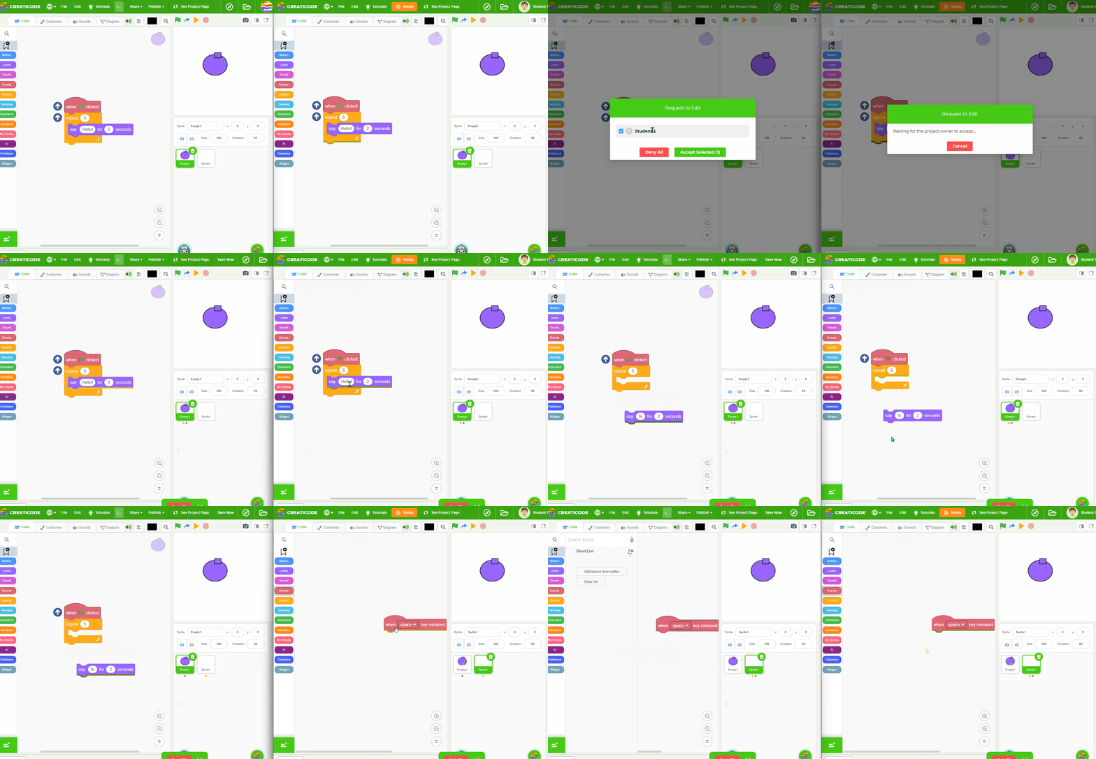
Acknowledged. This will be fixed soon. Thanks
Best posts made by info-creaticode
-
RE: Some avatars aren't shown to select until searched for
-
How to record and share screen recordings as gifs
Introduction
When you need to explain how a project should work, the best way is to make a screen recording of the stage. This short article will explain which tools you can use to record the screen, and also how to share the gif file to get a URL for it.
Screen Recording on Windows
If you are using a Windows computer, we recommend a free tool named “ScreenToGif”, which you can download here: https://www.screentogif.com/
Here is a short video explaining how to use it: https://www.yo utube.com/watch?v=ELfCBzN1Mtc
Screen Recording on Macbook
If you are using a Macbook, you can use a free tool called “Giphy Capture”: https://giphy.com/apps/giphycapture
Here is a short video showing how to use it: https://www.yo utube.com/watch?v=m-4cJMBGfS4
Share your gif file
Once your gif file is ready, you can share it this way:
-
Go to the “My Stuff” page at https://play.creaticode.com/mystuff, and make sure you are logged in.
-
Select “My Files” tab on the bottom left
-
Click the “+Share a New File” button on the top right
-
In the pop up window, click “Click to upload file”, and then select the gif file from your computer.
-
Click the green button that says “upload and share with the CC Attribution license” at the bottom.
After that, you will see the new file in the list of files, and then you can click “Copy file URL” button for that file, which will copy the URL to the clipboard, which would look like this: https://ccdn.creaticode.com/user-files/BfemEPCxatY6MMAPs/castfireball.gif
-
-
Wishlist for New Models
If you are looking for a particular 3D model that is not in our library, please reply to this topic. If you can include an example picture of it, it would be more clear what you are looking for. We will try to fulfill these requests as best as we can. Please make sure you do not submit duplicate requests by searching for it first.
Thanks
CreatiCode Support -
RE: Current error with accessing the website
Hi all,
Sorry there was an outage on our platform earlier this morning. Sorry about the inconvenience. Now we are back online.
CreatiCode
-
RE: Code block presets?
You are right. We should allow users to submit new extensions.
However, the code snippet library should be more like backpack than extension, since it will allow users to modify the code blocks after a snippet is imported. If it is an extension, then users won’t see its implementation and also won’t be able to customize it.
-
Shape-Based Particle Emitters
Introduction
You learned about Single-Point Particle Emitter, which generates particles from a single point in the 3D space.
In this article, we will discuss “shape-based” emitters, which generate particles from within a 3D shape like a box. They allow us to produce very different visual effects.
Box Emitters
The box emitter is simply a transparent 3D box, and it can generate new particles from any random point inside this box. We can not see this box since it is transparent, but we can indirectly see its shape by where the particles are generated.
To use the box emitter, we need 2 steps:
- Select the “Box” shape when creating the emitter
- Configure the size of the box by its minimum and maximum X/Y/Z positions
Here is a simple example:
This program creates a box emitter that is 400 units in each dimension. For example, in the X dimension, the minimum is -200 and the maximum is 200, so the x position of new particles can be any random value between -200 and 200. When you run this program, you can see the particles are all confined within this box-shaped region:
Sphere Emitters
The shape of the emitter can also be a sphere. When we configure the sphere shape, we can set its size using the “radius” parameter.
There is also a “range” parameter (between 0 and 1), which controls the range of possible values along the radius. You can think of “range” as “thickness”:
- When “range” is 0, the particles will only be generated on the surface of the sphere, and not inside it.
- When “range” is 1, the particles can be generated at any random point on the surface or inside the sphere.
- When “range” is between 0 and 1, the particles will not be generated near the center of the sphere, but can be generated on the surface or near the surface.
Here is an example program with a range of 0:
As shown, particles are only appearing on the surface of the sphere:
Hemisphere Emitters
Hemisphere emitters generate particles from a half-sphere shape. You can specify its radius and range the same way as the sphere emitters.
One thing special about hemisphere emitters is that we can rotate the half sphere to different directions. As shown below, when we rotate it around X-axis for 90 degrees, the new particles are all generated at the bottom half of the sphere:
Cylinder Emitters
The emitter can also take a cylinder shape. We can control the radius of the circle, and also the height of the cylinder.
The “range” parameter also works for cylinders. You can think of it as controling the “thickness” of the cylinder’s skin. For example, when radius 0.5, the thickness of the cylinder skin is half of the radius:
The cylinder shape also supports an additional parameter of “direction randomness”. This only matters when we set the particles to not face the camera all the time, and we will see the particles facing different random directions when we set “direction randomness” to 100:
Lastly, we can rotate the cylinder emitter as well. For example, we can make it “lie down”:
Cone Emitters
For the cone-shaped emitter, we can console these parameters:
- Radius: The radius of the bottom circle of the cone
- Angle: The opening angle of the cone. Note that the angle and the radius would imply the height of the cone, so we won’t need another “height” parameter.
- Radius Range: This range value applies along the radius direction. When it is 0, the particles will only be generated on the surface of the cone. When it is 1, the particles may come out from anywhere inside the cone or on its surface.
- Height Range: This range value applies along the height of the cone. When it is 0, the particles will only emerge from the bottom of the cone, and when it is 1, the entire height can generate particles.
We can rotate cone emitters as well.
-
RE: Multiplayer 3D games
We are working on fixing the cloud blocks. Should be within next few days. Sorry about that.
-
Number of Seconds since 2000
Introduction
In MIT Scratch, you can already manage dates using the “days since 2000” block. However, if you need a more granular control of date and time, you can use this new block:
This block will return the number of seconds that have passed between the given timestamp and the beginning of 2000.01.01.
Input Format
The input is a timestamp, which contains the date, a “T”, and then the time. The date is represented as year:month:day. The time is represented as hour:minute:second. Each field has to be 2 digits, except that the year has to be 4 digits.
The timestamp is assumed to be the local time of the computer that’s running this program. If you want to use the UTC time, which is the same across the world, then append a “Z” at the end of the timestamp, such as “2024.01.01T10:00:00Z”.
If the input is left empty, then the current time is used:
Calculating Time Difference
With this new block, you can easily calculate how many seconds are between 2 timestamps. You just need to run this new block for both timestamps, then calculate the difference between them:
Converting to Date
You can also convert the number of seconds back to a Date object. For example, the program below first gets the number of seconds for a specific timestamp, then create a date object using that result, and we get the same timestamp as our input:
-
RE: Issue.
@luna
Well, we are a small team, and we have many more urgent tasks on the list.
-
3D - A Spinning Earth (Difficulty: 1)
Key Topics Covered
Introduction
In this tutorial, you will learn to create a spinning Earth:
Step 1 - Initialize An Empty Scene
First, create a new project, and load an empty scene using the “initialize 3D scene” block.
By default, it will create an empty scene with nothing but a blue background:
Step 2 - Set the Background Starfield
Next, use the “set sky” block to create a better-looking backdrop:
You should get a starfield with the Sun on the right.
Step 3 - Add a Big Sphere
Next, add a sphere with a large diameter of 10000 to the scene. Don’t worry about its color yet.
The sphere would look brighter on the side that faces the Sun.
Step 4 - Add Earth Texture
Now we need to update the sphere’s texture with the Earth. Add the “update texture” block, click the “Please select” input box, then search for “Earth” in the library window.
Step 5 - Flip the Earth Texture
You might have noticed an issue with the texture: the continents are upside-down. We need to flip the texture vertically to correct this issue. This can be done by changing the vertical repeat count from 1 to -1.
Step 6 - Make the Earth Spin
To make the Earth object spin, we can use the “set speed” block. Note that the Earth needs to be spinning from “left” to "right, so the “Z-rotation” speed needs to be negative.
Now your Earth object should be spinning slowly.
Step 7 - Highlight Around the Earth
Lastly, to make the Earth object glow in blue lights, we can create a new highlight layer, then add the sphere to that layer.
Now your Earth object should carry a blue light around it.
Next Steps
You can try to use a similar method to build other projects. Here are some example ideas:
- A Different Planet: You can change Earth to other planets like Mars;
- A Spinning Trophy: You can try to make a trophy object spin and shine.
Latest posts made by info-creaticode
-
RE: Feature Suggestions: Integration of Scratch Addons
It looks like the original Scratch Addons only work on MIT Scratch, and it has about 170 addons. To use them you have to install the officla chrome extension.
Then turbowarp has adopted about 75 of these so that you can run them on the turbowarp editor.
Any top addons you would like to be supported? If the turbowarp subset is good enough, we might do something similar to turbowarp.
-
RE: Feature Suggestions: Integration of Scratch Addons
We will do some research on how to support Scratch addons. Thank you for the suggestion.
-
RE: How do I delete an account?
You can email your account’s email to info@creaticode.com, so we will delete it for you.
-
RE: Clone Detections - help
Currently there is no code to directly do this. You probably need to calculate their distances and find which one is “too close”
-
RE: Position bugs near the edge on a larger box than normal
The issue might be that the current code is highly “inefficient”. It is repeatedly erasing the bar and redrawing it, even if the health has not changed. Usually, you only need to redraw it when the health has changed.
-
RE: Drawing a loading circle without sprites - help
The draw oval block can only draw full circles, not partial ones.
Why you can’t use sprites?
If you can’t use sprites, can you use the Pen blocks to draw the circle segment by segment?
-
Self-Driving Car AI - Following Driving Directions (Difficulty: 4)
Introduction
After the previous tutorial, our AI driver can automatically control the car to stay in lane, limit its speed, stop at the stop sign, and turn right at a crossing.In this tutorial, we will extend it further so that it can follow a list of driving directions to turn left/right or go straight.
Step 1 - Remix the Starting Project
Please remix the following project:
play.creaticode.com/projects/67ad8b0919667583370d2d81
Note that the AI sprite contains the same logic from the previous tutorial, but the blocks have been divided into a few custom blocks to make them more readable:
Step 2 - The “driving directions” list
For a self-driving car in the real world, it will typically receive a destination from the passenger first, and it will calculate a driving direction based on that.
We won’t get into how to calculate the driving direction in this tutorial. Instead, we will assume the directions have already been calculated, and we will represent them using a list named “driving directions”.
Each item in this list will be a letter, which represents the direction at each crossroad:
- L: turn left at the next crossroad;
- R: turn right at the next crossroad;
- S: go straight at the next crossroad;
For example, suppose the driving directions list contains these 3 letters:
That means the car is expected to turn left at the next crossroad, go straight at the crossroad after that, turn right at the third crossroad, and then stop there.
Step 3 - Read the next direction
To keep our AI code simpler, we would only focus on the first direction from the list. After it is completed, we move on to the next direction on the list.
We can use a new variable “next direction index”, which represents the index number of the next direction we have to follow. We will need to initialize this variable to 1 at the start:
We will use another new variable “next direction” to represent the actual direction. We will initialize it at the start as well, and we will update it after this direction has been fulfilled:
Step 4 - Check for the lane on the left
In the “normal” driving mode, we need to prepare for the next turn. For example, suppose the next direction is “L” for a left turn. If there are 2 lanes and our car is on the right lane, we need to switch to the left lane first, since we can not make a left turn from the right lane.
To find out if there is another lane to our car’s left, we can use the “marker info” table, and look for the marker named “left marker”. If it exists, that means there is another lane to the left going in the same direction.
Let’s define a new custom block named “update marker”, and run it at the beginning of the normal mode handler:
In that block’s definition, whenever the next direction is “L”, we will get the index of the “left marker” from the “marker info” table:
Step 5 - Temporarily change the lane marker
Suppose we have found another lane to our left, how do we ask the car to switch to that lane? The solution is very simple: we just need to aim at the lane marker from that lane, until the car enters that lane. After that, assuming there is no other lane on the left, our car will resume the old logic of following the lane marker in this new lane it has just entered.
In code, we check if the index of the “left marker” is greater than 0, and if so, we would temporarily set the “marker angle” to be the angle relative to the marker in the left lane, not the current lane:
That is all we need to make the car switch to the left lane. You can see that the “left marker index” is 2 when there is another lane on the left, and it changes to -1 right after the car enters the new lane. After that, the car reverts back to the normal mode of aligning to the lane marker in the lane.
Step 6 - A new driving mode of “turnleft”
To make the car turn left, we need a new mode of “turnleft”, similar to the “turnright” mode.
Currently, when the AI is in “stopsign” mode, it always switch to the “turnright” mode after the car has fully stopped. We need to change that to determine which mode to use based on the next direction. The new “target dir” will also be different when the car needs to turn left: it will be the current direction of the car minus 90 degrees rather than plus 90 degrees.
Step 7 - Handle the “turnleft” mode
We will define a new custom block to handle the logic of turning left at a crossroad, similar to the “handle turn right” block.
To make the car turn left, we can reuse the same code for turning right, but change the engine force and steering angle. Can you give it a try?
[please try it yourself before looking at the next step…]
Step 8 - The logic for turning left
You should see that turning left involves a larger turn with a longer radius. There are many ways to set the engine force and the steering angle, and one example solution is the following, where the engine force is 10 and the steering angle is -9.5:
This is what we will get now:
Step 9 - Move on to the next driving direction
After the turn is completed, when we switch back to the “normal” mode, we should also update the “next direction” to the next item in the list:
Note that this needs to be done in both the “handle turn left” and “handle turn right” blocks
Additional Challenges
At this point, our AI can drive the car to switch to the left lane and also follow the driving directions to turn left or right. There are a few missing pieces, so please use them as practice:
-
Handle “go straight”: If the driving direction is “S”, the car should go straight across the crossroad. Please add logic to handle this case. For a hint, you can use the car’s distance from the starting point of the lane ahead (the “forwardxy” column of the lane marker) as a threshold: if the car is close enough to this point, you can switch back to normal mode.
-
Switch to the right lane: when the next direction is “R”, and our car is still on the left lane out of 2 lanes, it should switch to the right lane.
-
Stop at the end: when all the driving directions on the list have been fulfilled, the “next direction” becomes empty, then the car should switch to the right lane if it is not in that lane and then stop.
You can test your AI with a list of directions like this: L, S, R, R, S, R, R, S
-
RE: feature request: DeepSeek AI blocks
We reviewed DeepSeek, but it does not meet our safety requirements yet. It has only implemented a minimal safety guardrail, so we can’t support it in our platform at the current stage.
-
Self-Driving Car AI - Making Right Turns (Difficulty: 4)
Introduction
In the previous tutorial, we created an AI driver that can steer the car toward the center of the lane with the help of a lane marker.In this tutorial, we will make the car stop at the stop sign at the end of the current street and then make a right turn.
Step 1 - Remix the Starting Project
Please open the following project and remix it into your own:
play.creaticode.com/projects/67abea71019e21d07d95ed17
In this project, the AI sprite already contains the logic from the previous tutorial:
When you click “Start”, the car will go back into the center of its lane, and stop after 5 seconds. We will use this code as our starting point.
Step 2 - Read information about the stop sign
The stop sign is a very important object. It not only tells us where is the end of the current street, but also requires our car to make a full stop. However, we should not deal with stop signs unless we are close to one, otherwise it will be a waste of time to constantly review all stop signs on the map.
For this purpose, our simulation environment provides the following information to the AI driver:
- When the lane marker arrives at the stop sign, it will stop moving forward, and also turn red.
- In the “marker info” table, the column “stop” will become 1 when the lane marker stops at the stop sign.
- In the “marker info” table, these 3 columns will tell us the starting point of the next lane if the car needs to turn left/right or continue forward.
Now let’s observe these information by running the program. When you click the “Start” button, you will see the the lane marker will stop moving at the stop sign and turn red:
At this point, turn on the monitor of the “marker info” table, and you will see these columns on the right:- stop: this column is 1 when the lane marker is stopped at a stop sign, and empty otherwise;
- leftxy: this is the x and y positions of the starting point of the next lane if the car needs to turn left. It is empty when there is no way to turn left or when that information is not provided.
- forwardxy: this is the x and y positions of the starting point of the next lane if the car needs to continue forward. It is empty when there is no way to continue in the same direction or when that information is not provided.
- rightxy: this is the x and y positions of the starting point of the next lane if the car needs to turn right. It is empty when there is no way to turn right or when that information is not provided.
As you can see, “stop” is 1, indicating the lane marker is at a stop sign. Also, the “rightxy” column is “260_2427”, which means for the car to turn right, the next lane will start at the position of (260, 2427).We can add 2 new variables that are related to the stop sign:
- is stop: whether the lane marker is stopped at a stop sign;
- distance: distance to the lane marker;
Next, we will use this information to control the car.
Step 3 - The Driving Mode
To make our car stop at the stop sign, our AI will give different commands to the car than to make the car go forward. To clearly indicate what our AI driver is doing, we will use a new variable “driving mode”, which will have these values:
- It will have a value of “normal” when the car is going forward
- It will have a value of “stopsign” when we need to stop the car for a stop sign.
When the AI driver starts, it will be in the “normal” mode:
And we will use 2 “if” statements to organize our logic based on the driving mode:- If the driving mode is “stop sign”, we set the brake level to stop the car
- If the driving mode is “normal,” we apply our existing logic of keeping the car in the lane center and under the 100 speed limit.
Step 4 - Switch to the “stopsign” driving mode
We are still missing an important logic: how do we switch from the “normal” mode to the “stopsign” mode?
While we are driving the car normally, we need to keep an eye on the stop sign information. If the lane marker has stopped at a stop sign, and if our car is very close to the lane marker (distance < 80), then it is time to switch to the “stopsign” mode. In code, this logic is the following:
Now our logic for stopping is complete. We no longer depend on the timer value, and the car automatically stops before the stop sign.
Step 5 - Switch to the “turnright” driving mode
After the car has stopped, we need to make the car turn right. We can introduce a new driving mode of “turnright”, so that we can put all the code for turning the car right in that mode.
We need to carefully consider when to switch to the “turnright” mode. There are 2 issues we need to handle:
- When the AI set the brake level to 100, the car may not immediately stop. Depending on its speed, it might take some time to come to a full stop.
- Even after the car has fully stopped, we should not start the right turn right away. It is better to wait some time.
To handle these issues, we can use the following logic to switch from the “stopsign” mode to the “turnright” mode. Basically, we will wait until the car’s speed is almost 0 (less than 1), and then wait another 1 second, and then switch to the “turnright” mode.
Step 6 - Make the car turn right
Now we can start to add logic to control the car in the “turnright” mode. To start simple, we can simply set a small engine force and steer the car to the right by 25 degrees:
Now let’s observe what happens:
Our AI has successfully made the car turn right. Next, we will need to think about when to exit the “turnright” mode so the car can drive normally on the new street.
Step 7 - “car dir” and “target dir”
One simple way to determine if the car has fully turned right is to check if its direction is aligned with the new street’s direction.
First, let’s add the “car dir” variable, which will store the direction of the car (read from the “car info” table):
Next, when we switch to the “turnright” mode, we can use another variable “target dir” to store the desired driving direction of the car, which is the current direction of the car plus 90 degrees (since we are turning right by 90 degrees):
Step 8 - Compare “car dir” and “target dir”
The last step is to keep checking if the car’s direction is aligned with the target direction, and when that happens, switch back to the “normal” driving mode.
To do that, we can first calculate the absolute difference between the car’s direction and the target direction. The “abs” operator ensures we only look at their difference, and it does not matter which value is greater.
Next, if the direction difference is very small, then we can switch back to the “normal” mode:
Note that we also check if the direction difference is greater than 355. This is because the direction value is always between -180 and 180 degrees, so if 2 directions are 179 degrees and -178 degrees, their difference is 357 degrees, but they are actually only 3 degrees apart.In summary, here is the full logic for handling the “turnright” driving mode:
Now our car will keep driving happily in a large square:
Additional Challenges
Here are some challenges for you to improve our AI driver further:
- Currently the car will cut into the corner of the curb. Can you improve the “turnright” mode further so the car makes a clean right turn?
- Can you try to make the car turn into the left lane in the new road? It is the lane with the yellow line on its left, which requires a bigger turn for the car.